And Logic Gate Circuit Diagram Transistor
Logic gate: types including circuit diagram, symbols and uses Gate transistor circuit logic terminals reminder input two Gate transistor logic circuit gates diagram xor petervis transistors using ttl bipolar gif animation
transistors - Can anybody explain how the inverter circuit works
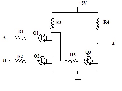
Emitter-coupled logic logic gate electronic circuit circuit diagram Logic circuit transistor gate diagram coupled emitter electronic And gate using transistor
Gate transistor logic gates input output circuits digital circuit transistors truth nand led build different made questions current electronics source
Transistor transistor logic gateGate transistor using circuit diagram improved schematic designing version circuits Gate transistor logic gates input circuit transistors truth table circuits digital simple inputs electronics tutorial structure output diagram using quantumDual logic transistor gates : 10 steps.
Transistor gate structure circuit question similarCircuit inverter transistor led switch gate logic gates transistors gif battery explain anybody works off petervis shouldn loop affect forms Electric circuits gate electronics digital circuit logic gates transistor transistors diagram electronic electrical function basic simple diodes power chapter fieldDigital logic.

Implementation of a not gate with two transistors
Or gate logic circuit using transistorsGate transistors two implementation transistor why electronics lower question need stack just Is this npn transistor and logic gate practical?Logic gates.
Digital electronics-logic gates basics,tutorial,circuit symbols,truthGate logic transistor npn practical circuit schematic Transistor logicTransistor logic gates gate voltage make use designing example would take stack.
Transistors circuit sparkfun gate bjt using input learn projects logic arduino electronics electrical inverter switches electronic built tutorials
The transistor level schematic of logic gates.Eee world, department of eee, adbu: digital logic or gate Designing or gate circuit using transistorLogic and gate tutorial with logic and gate truth table.
Where to get logic gate transistorsSchematic transistors logic gate where circuitlab created using Logic gates signal gate animation ttl gif circuit nand transistor homofaciens device off through input there if low technik bilderLogic transistor.

Gate logic types transistors using uses circuit principle working diagram
Transistor and gateXor gate transistor electroniques zpag english Gate circuit transistor logic inverter usingLogic transistor gates instructables transistors.
Transistor xor gateGate transistor using circuit diagram transistors based engineersgarage fig What is not gate inverter, not logic gate inverter circuit using transistorIs this npn transistor and logic gate practical?.

Transistor nand
Transistor logic and gateGate transistor logic npn schematic using circuit practical questions circuitlab created stack Logic gate schematic transistor resistor described truth given below table eee.
.


Logic AND Gate Tutorial with Logic AND Gate Truth Table

Emitter-coupled Logic Logic Gate Electronic Circuit Circuit Diagram

transistors - Can anybody explain how the inverter circuit works

Is this NPN transistor AND logic gate practical? - Electrical

Implementation of a NOT gate with two transistors - Why not one

Dual Logic Transistor Gates : 10 Steps - Instructables
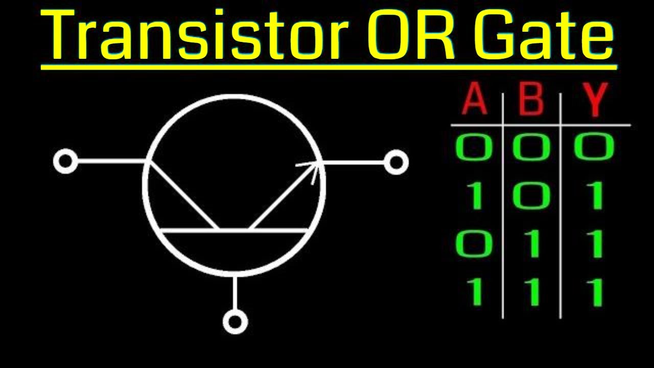
OR gate logic circuit using transistors | Transistor logic circuit