8 Bit Bcd Adder Circuit Diagram
Design 8-bit bcd. Adder bcd bit binary two diagram logic block adders combinational figure answer shows solved has help Adder bcd
BCD | All About Circuits
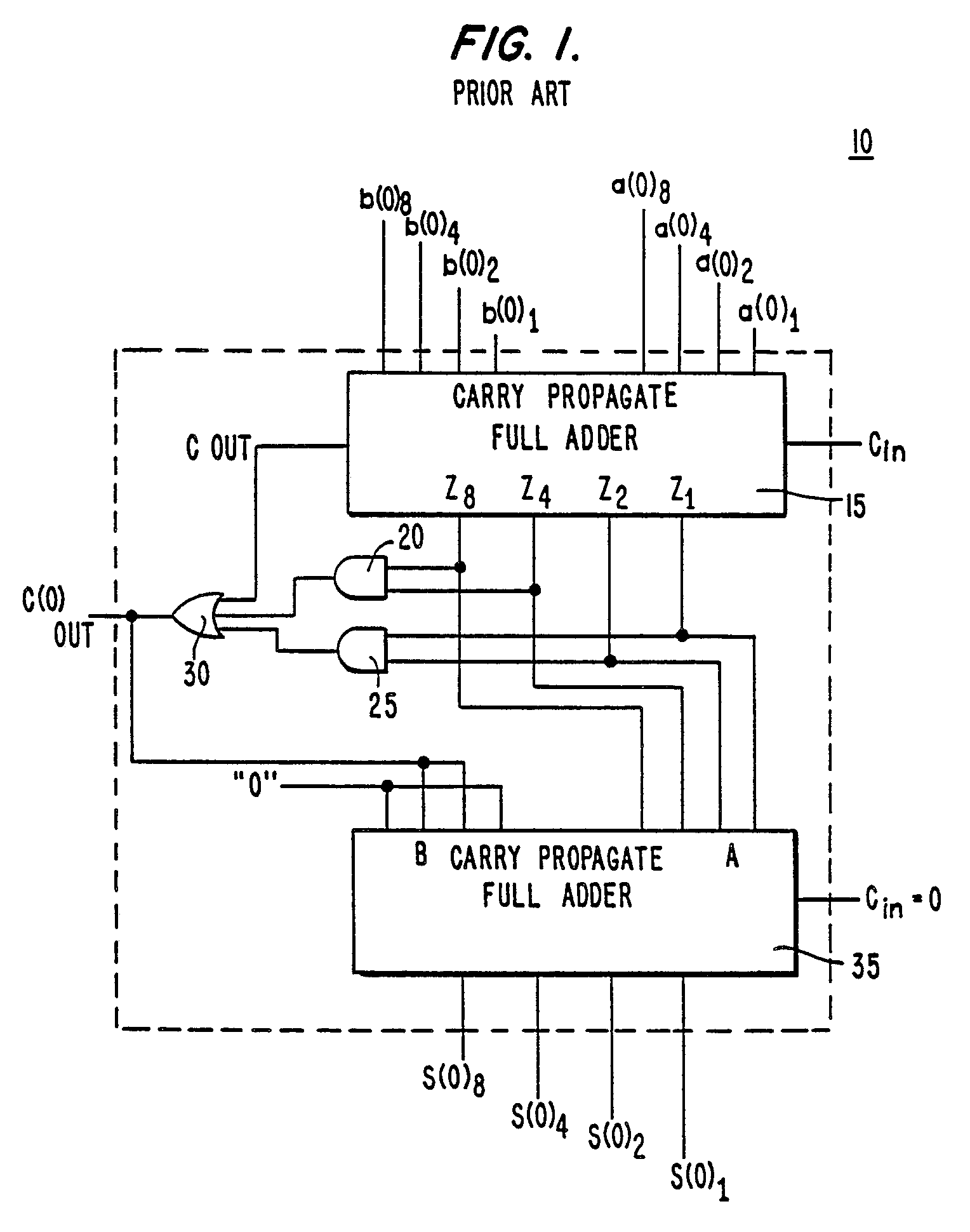
Bcd adder digit carry Patent ep0298717a2 Patents adder bcd circuit drawing
Ashan's blog: designing a bcd adder & subtractor with hdl
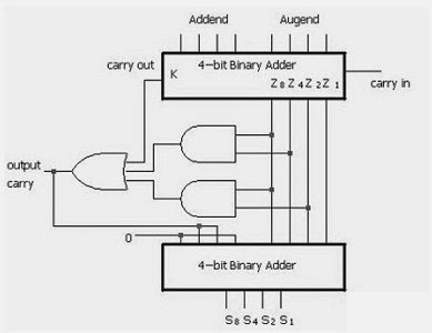
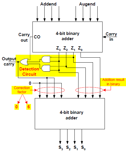
Digital logicSolved 1. the figure above shows a 4-bit bcd adder. you can Bcd adder circuitAdder xor rangkaian transistor ripple pengertian kombinasi.
Adder bcd 7483 using ic diagram circuit block draw neat sum case3 carry but explainAdder bcd 7483 ic using digit circuit output Bcd adder subtractor circuit bit logic using problem solved show block overflow digit use shows figure transcribed text been hasBinary multisim bcd gates logical convert logic converting.
Adder bcd logic circuit digital input two shown figure will
Bcd adder subtractor digit diagram binary addition ashan cin cout moduleSolved 1. the figure below shows a bcd adder. design Bit logic adder bcd alu vhdl digital digit unit program circuit detector schematic figure cs302Circuitverse adder bcd.
Adder bit parallel four circuit binary diagram block example detailed discussionBcd adder vhdl lab Designing of bcd adder circuitAdder bcd bit using binary digit two numbers implement logic diagram single block input carry shown digital fig together procedure.

Bcd adder circuitverse
😊 four bit parallel adder. 4 bit binary adder circuit / block diagramDraw a neat circuit of bcd adder using ic 7483 and explain. Bcd adderProposed 1-digit bcd adder circuit..
3 bit adder logic circuit designBcd subtractor circuit diagram Bcd adder care4youBcd bit adder diagram block add digit input.

Bcd subtractor adder circuit diagram connections units using
Bcd adderAdder bit circuit logic carry a1 a2 stackexchange b2 b1 xor Implement single digit bcd adder using 4-bit binary adder ic7483. showDesign a 1 digit bcd adder using ic 7483 and explain the operation for.
Bcd adder:2 digit bcd adder a 4 bit adder subtracter unit digital logicAdder bcd digit Full adder circuit diagramBcd subtractor adder schematics.
Digital logic design: bcd adder
.
.


BCD | All About Circuits

adder - Bcd subtractor units connections - Electrical Engineering Stack

Full Adder Circuit Diagram
Digital Logic Design: BCD Adder

Solved 1. The figure above shows a 4-bit BCD adder. You can | Chegg.com

digital logic - How to convert 8 bit binary to BCD using logical gates

CircuitVerse - Online Digital Logic Circuit Simulator